
This is a detailed guide that lays out all the parts, tools, and steps involved in assembling a panic button of your own.
- Before beginning, ensure you have all the necessary parts, tools & materials
- Printed Parts
- Shell
- Core (top & bottom halves)
- Lithophane panel
- Components & Materials (by vendor)
- Adafruit (link to wishlist containing all parts below)
- Massive 100mm arcade button (they come in several colors)
- 3xAA battery holder (w/ switch)
- Arcade button/switch quick-connect wires (0.25 and 0.187 in.)
- Diffused 10mm LEDs (need 4; whatever color you want)
- (2) 4-ohm 3-watt speakers (3 in. diameter)
- Push-button power switch breakout
- Little rubber bumper feet (4pk)
- DFRobot
- Digikey
- (5) 62 ohm resistors
- 4-ohm 3-watt speaker (alternative to the Adafruit ones above)
- (2) Through-hole electrolytic capacitors (nothing huge; I used a couple 10uF caps I had laying around)
- Other
- Adafruit (link to wishlist containing all parts below)
- Tools
- Soldering iron and heat-set insert tips (these, for example)
- Hot glue gun
- Metric hex driver set
- XACTO Knife
- Side cutters & wire strippers
- Pliers are always handy
- Code
- I’ve also included the OpenSCAD file I used to create the “PANIC” lithophane in the repo linked above.
- The PCB files can be found in the pcb/ directory of the repo.
- Printed Parts
- Printed part post-processing
- I’ve had good luck printing my panic buttons in PETG. While I’m sure PLA would work (and probably look better), I think PETG is a better overall choice given the need to thread screws directly into plastic parts as well as hot-press threaded inserts into the base of the core.
- PETG tends to be a bit stringy so you may find it useful to have a heat gun available to deal with that after printing.
- Due to the large, square overhangs for the button & battery holder in the core and lithophane window in the shell, support material is required during printing. Clean up supported areas as best you can, but know that at least in the case of the button and battery holder recesses, it’s not mission-critical to achieve perfection. On the other hand, the shell’s lithophane window does need to be free of any stray support material or loose filament strands, else the lithophane will not fit.
- The lithophane should just snap into the shell (and be nearly flush with both the inner and outer surfaces). If you’re having trouble with this, make sure there’s no support material left in the shell’s window.
- Additional printing tips can be found alongside the STL files on Printables.com.
- Warm up by sticking the rubber feet to the bottom of the shell.
- They fit nicely in the corners (just make sure you’re not covering up the screw holes at all).
- Shell warped during printing but otherwise still usable? The feet should help make up the difference and stop the finished panic button from rocking off your desk.
- Press the brass threaded inserts into the core-bottom
- Install the threaded insert tip on your soldering iron and get it hot (for PETG, I heated mine to 445° Fahrenheit — about 230° Celsius).
- Put a threaded insert on your iron tip and firmly press it into one of the holes in the battery holder side of the core-bottom.
- Keep the iron as perpendicular to the bottom surface of the core as possible to ensure the insert follows the hole.
- Don’t press too hard; let the iron do most of the work.
- It’s important that the hole be free of all support material or you’ll have a hard time pressing the insert in.
- Once each insert is flush with the core bottom, press the core onto a hard, heat-proof surface to ensure no plastic bulging occurs (I used a metal square as shown above).
- When done, be sure to turn your iron off to let it cool.
- Set all printed parts aside for now.
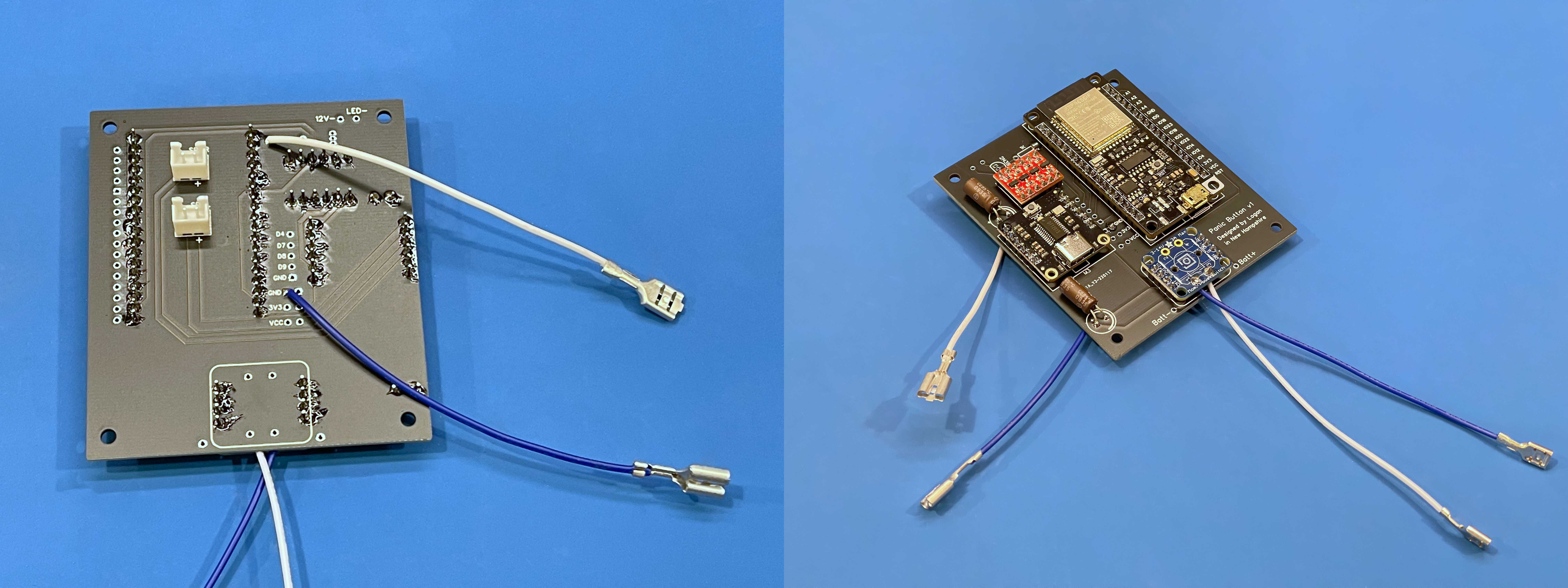
- Cut the arcade quick-connect wires
- For the set with larger spade terminals, cut approximately 4.25 inches from the JST connector. These wires will connect the button LED and right speaker to the mainboard.
- For the set with smaller spade terminals, cut the wires halfway between the JST connector and spades. These wires will connect the button switch and left speaker to the mainboard.
- Replace the built-in button-LED resistor
- The LED comes wired for 12 volts but we want to turn it on with a 3.3v microcontroller pin.
- The LED and its resistor are attached to an automotive bulb-style cartridge (the red tube) in the button stalk; pull it out.
- Unwrap the leads from the plastic tabs and pull out the LED.
- Unsolder the resistor and solder a 62 ohm resistor in its place.
- Wrap the leads back around the plastic tabs and reinsert the bulb assembly into the button stalk.
- To make final button assembly easier, it would be a good idea at this point to test which of the “bulb’s” leads is the anode and make a mark on that side of the plastic tube.
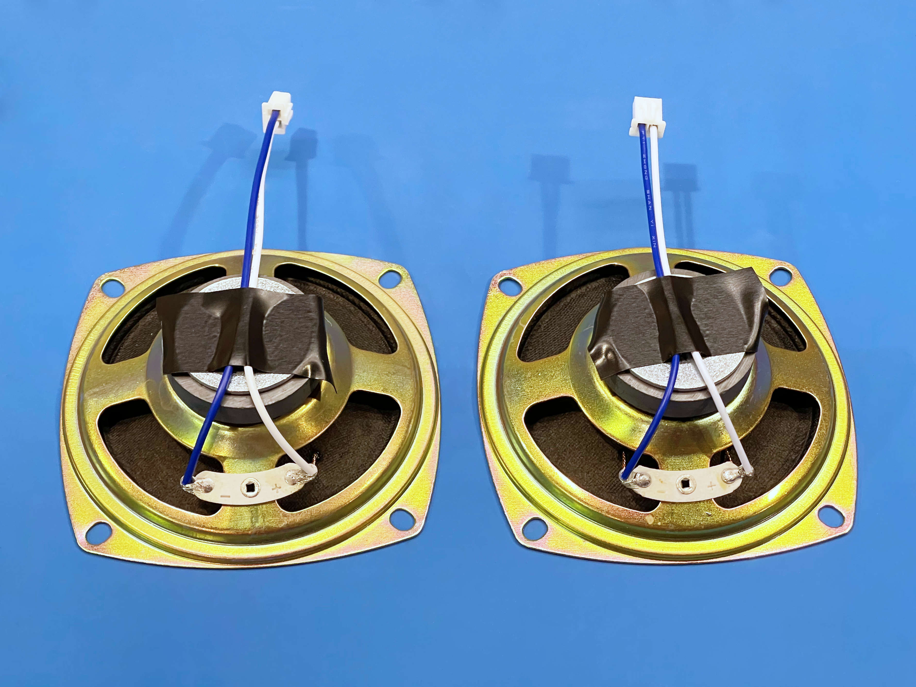
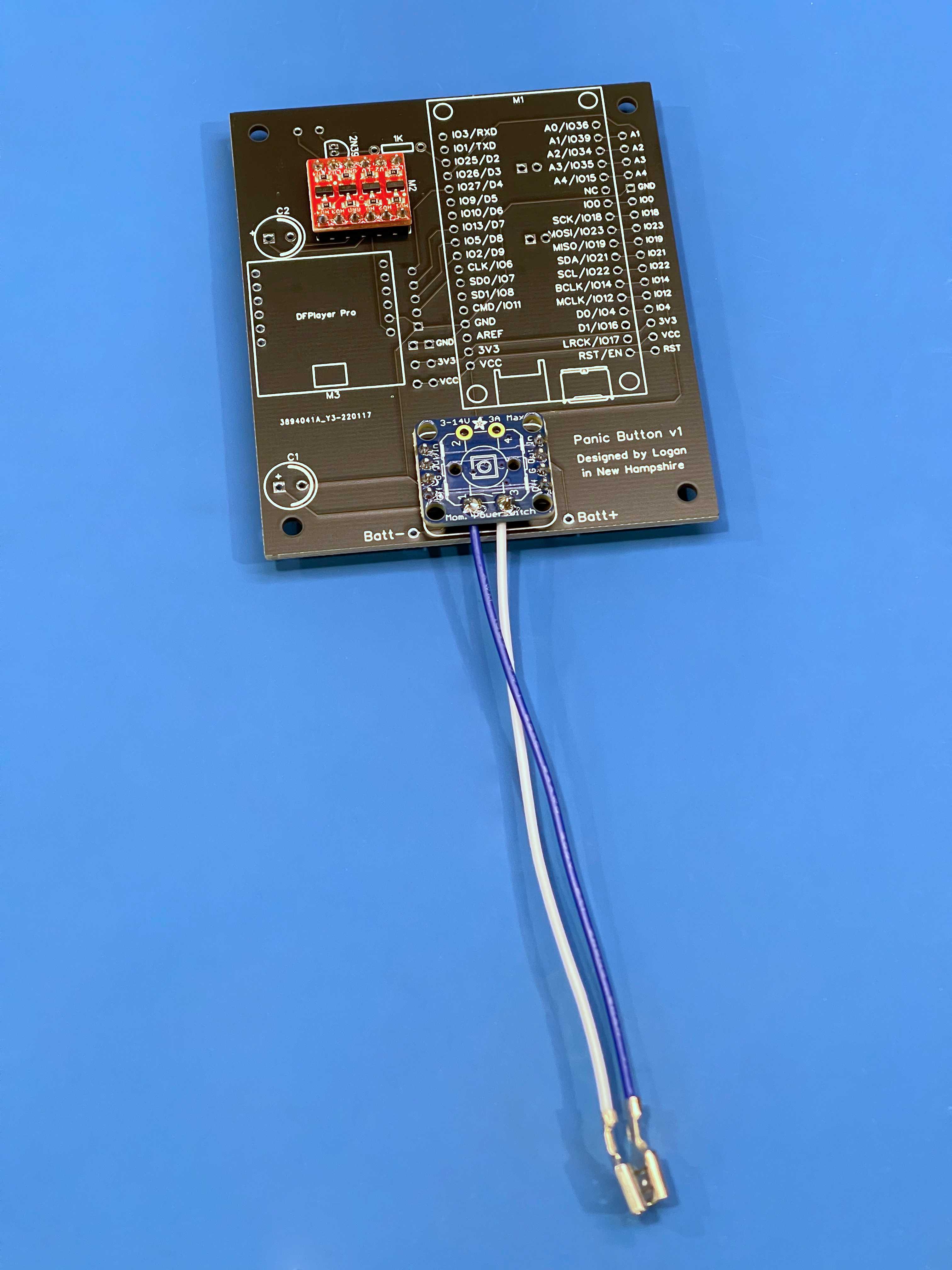
- Solder the freshly cut JST connector wires to the terminals of the speakers
- Whichever color wire is pinned in the right side of the JST connector (when viewed from the “back”/wire-side with the indexing pins on top) should be soldered to the positive terminal of the speaker.
- In my case, this meant the white wires connected to the positive speaker terminals and the blue wires went to the negative speaker terminals.
- I’ve found electrical tape to be helpful for this process (see image).
- Set the wired-up speakers aside for now.
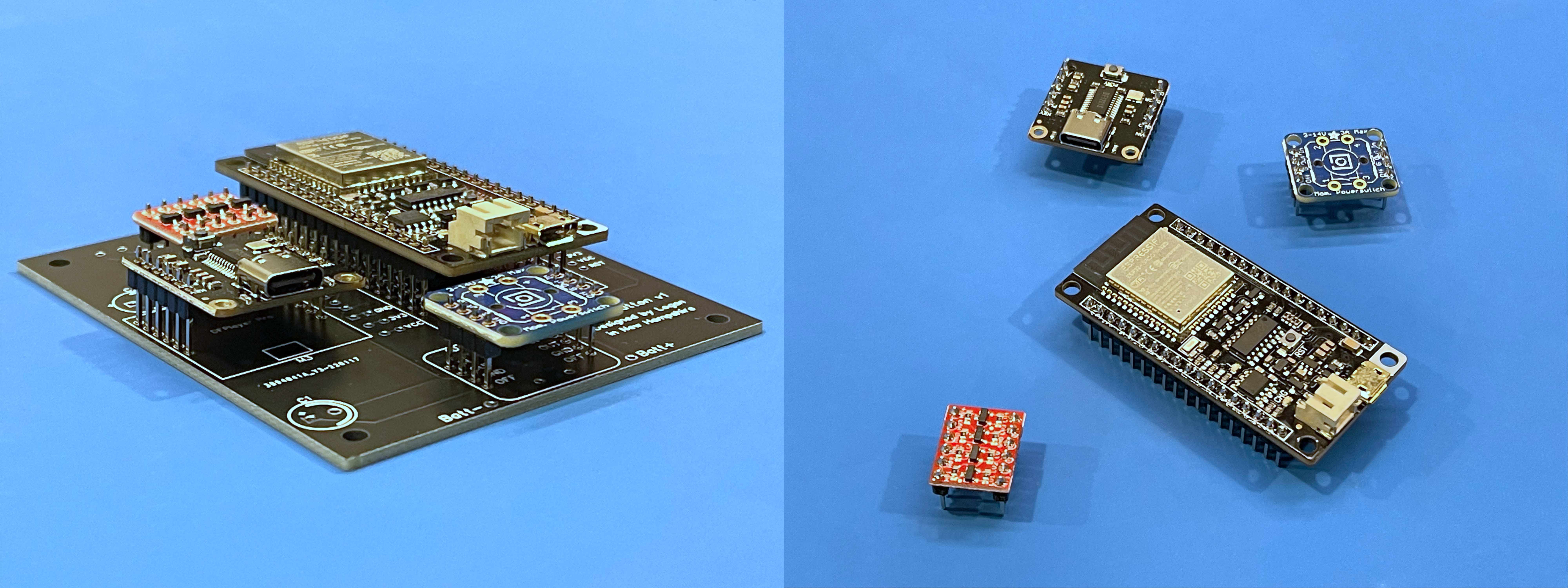
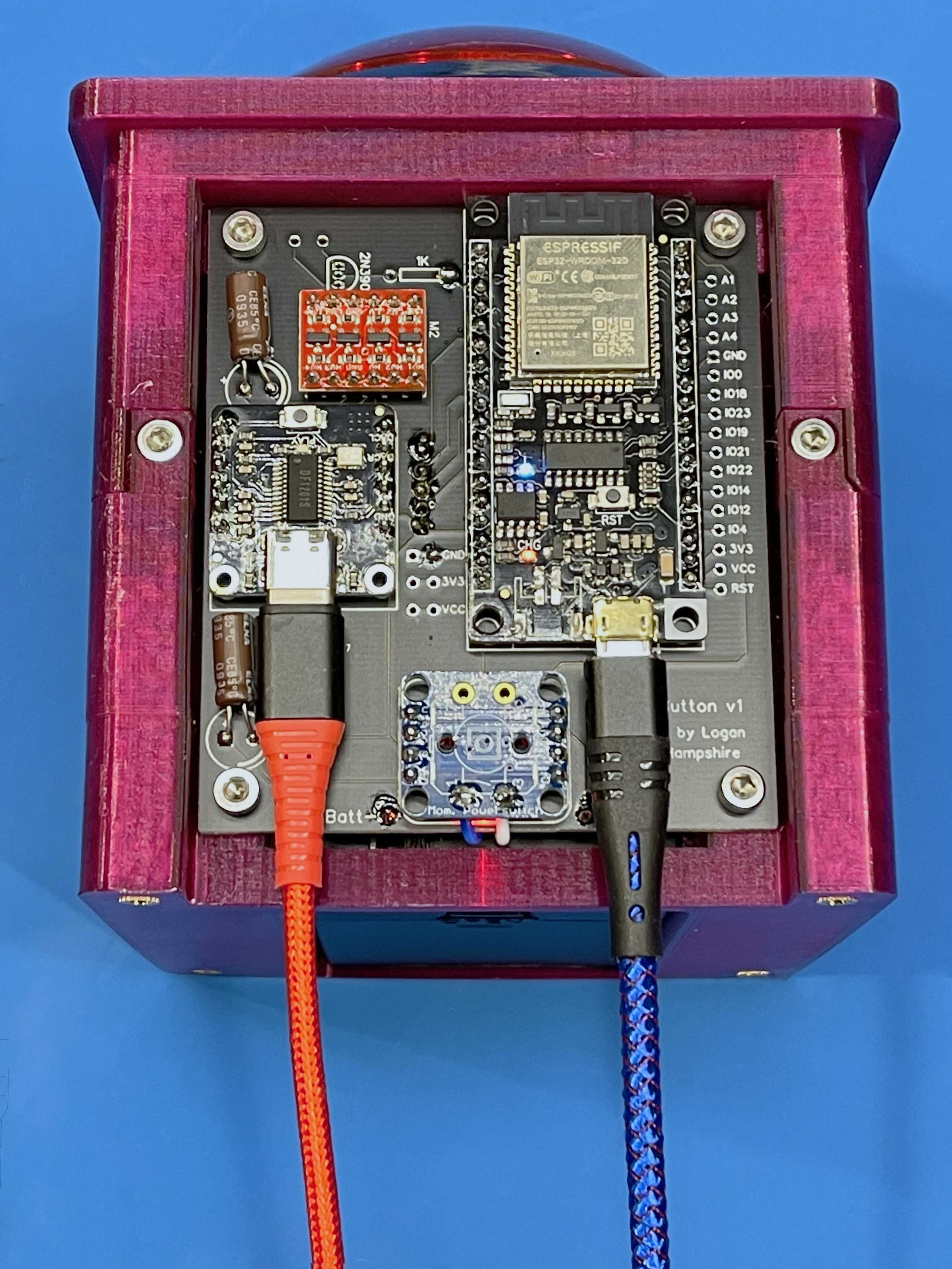
- Solder male header pins to the FireBeetle, DFPlayer Pro, level shifter, and latching power circuit
- I like to hold the header on each module and set them down into the correct holes in the mainboard on my bench. This ensures the two strips are kept evenly spaced (though care must still be taken to avoid soldering the two strips askew).
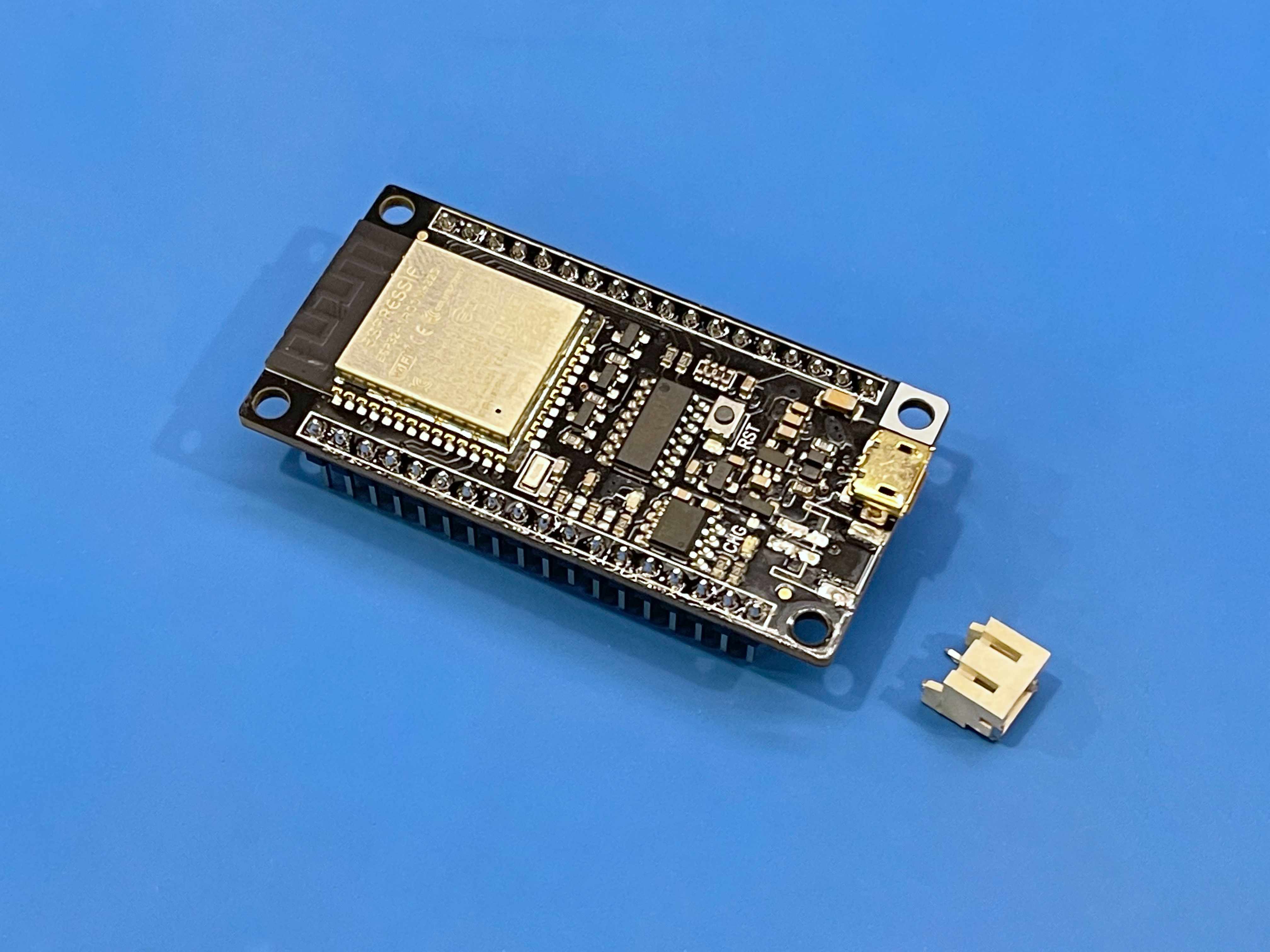
- Desolder the battery connector from the FireBeetle
- It’s the tallest thing on the board and we’re not going to need it.
- Be careful not to take anything else out in the process of removing the connector.
- The core won’t fit into the shell with this connector attached so this step is not optional.
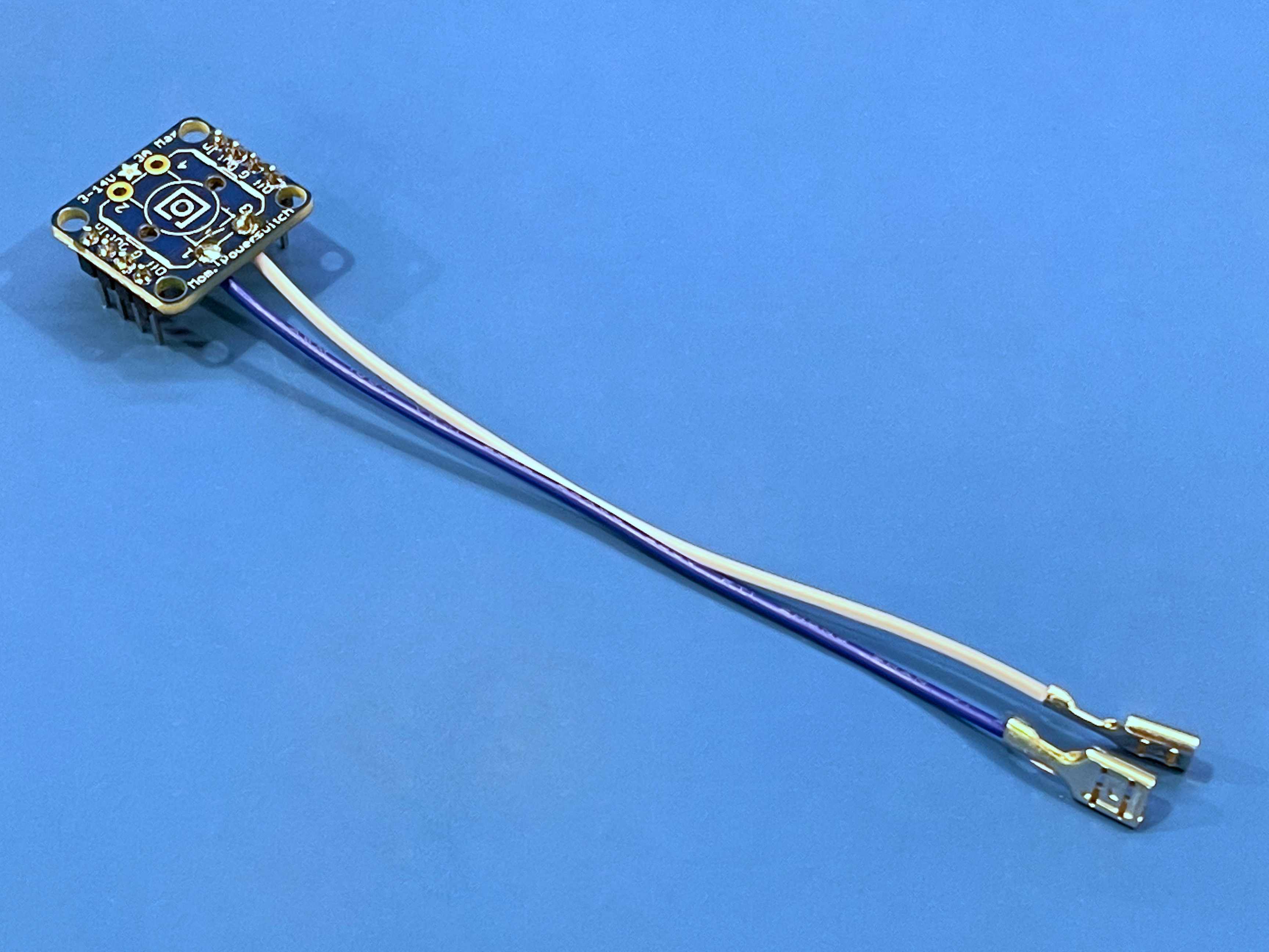
- Solder the wires with the smaller spade terminals from step #5 to pads 1 & 3 on the latching power circuit
- You can attach them from either side, but I tend to prefer going from the same side as the header pins.
- Solder the level shifter and latching power circuit modules onto the mainboard
- Make sure both are oriented correctly.
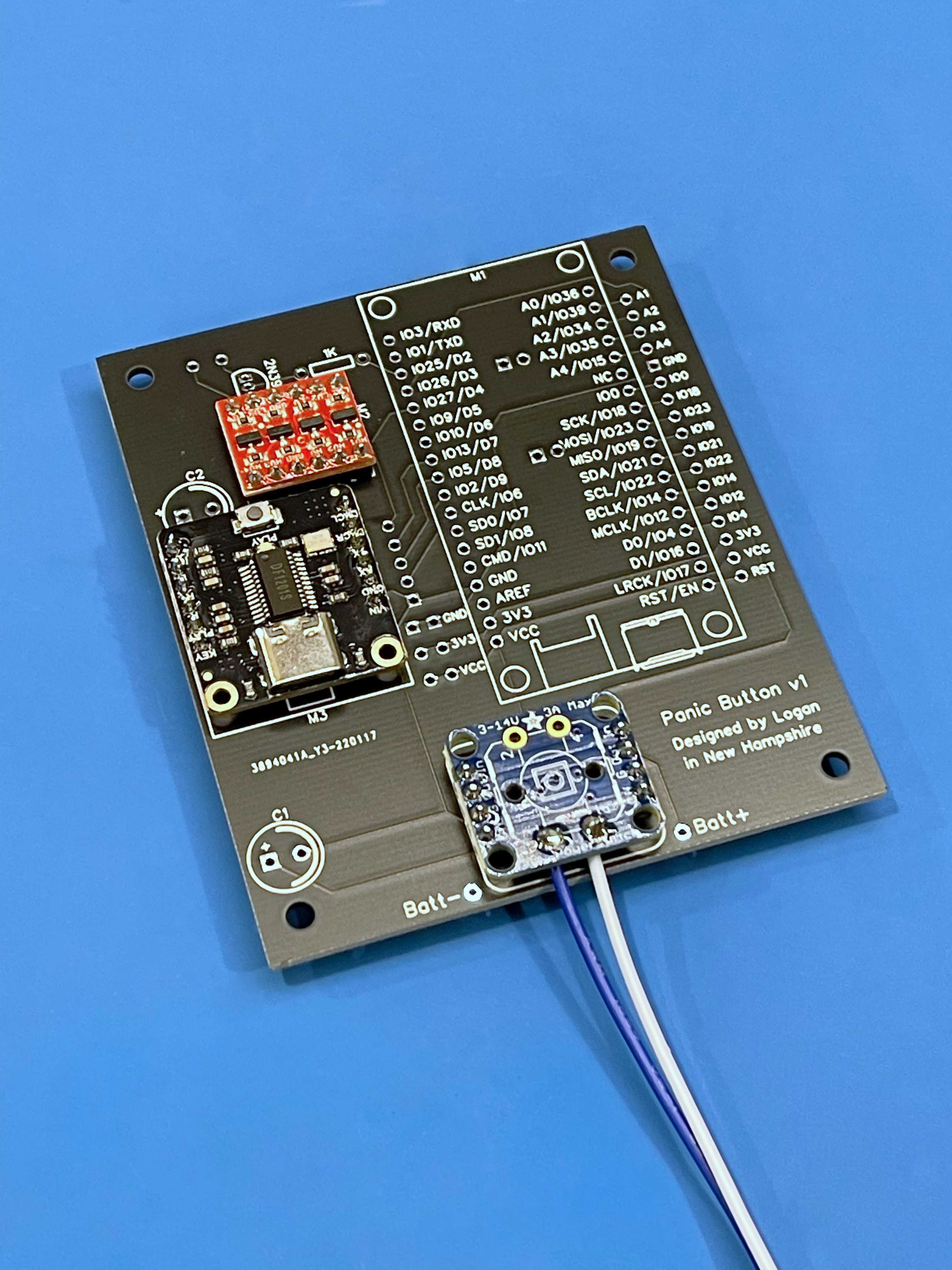
- Solder the DF Player module to the mainboard
- Make sure it’s fully seated against the board.
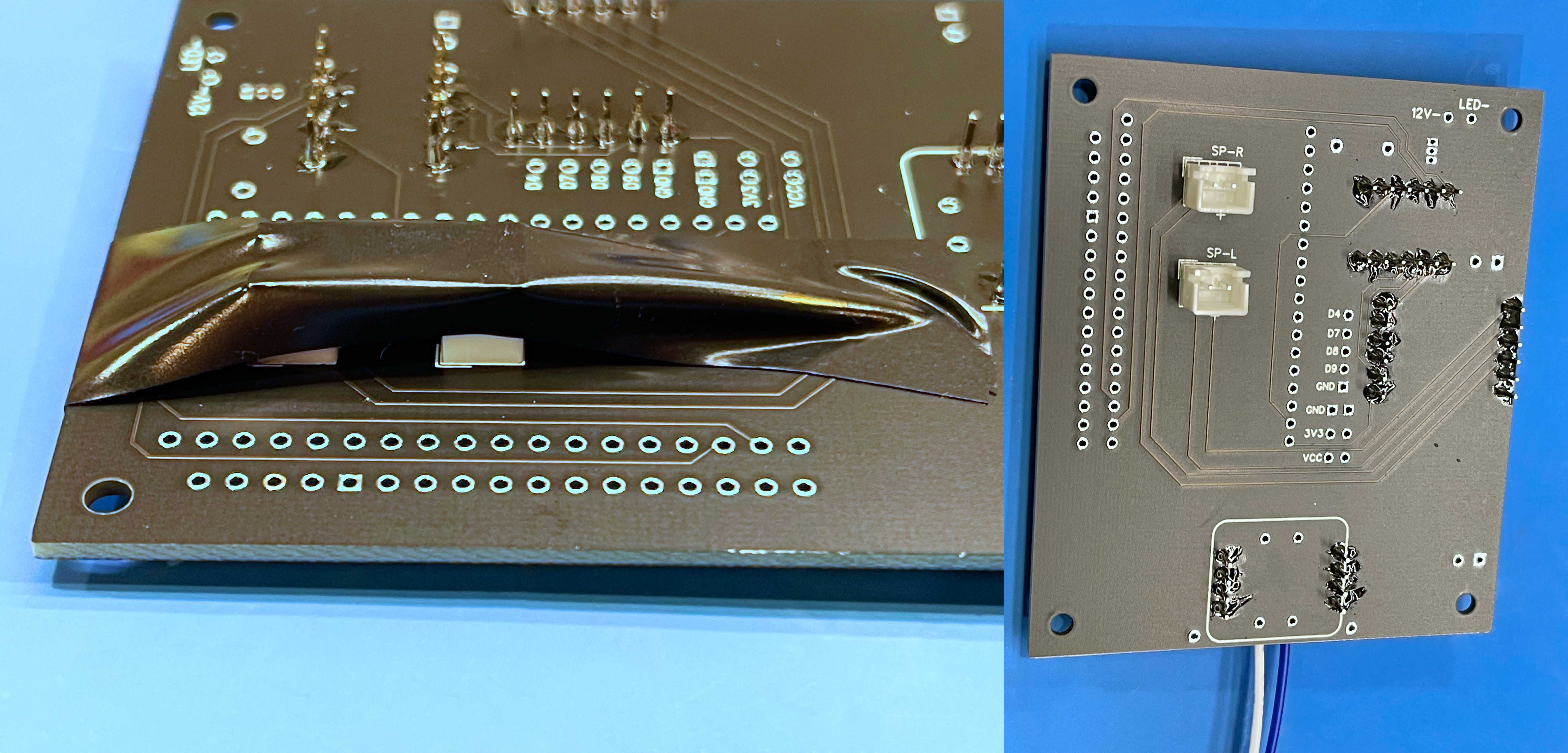
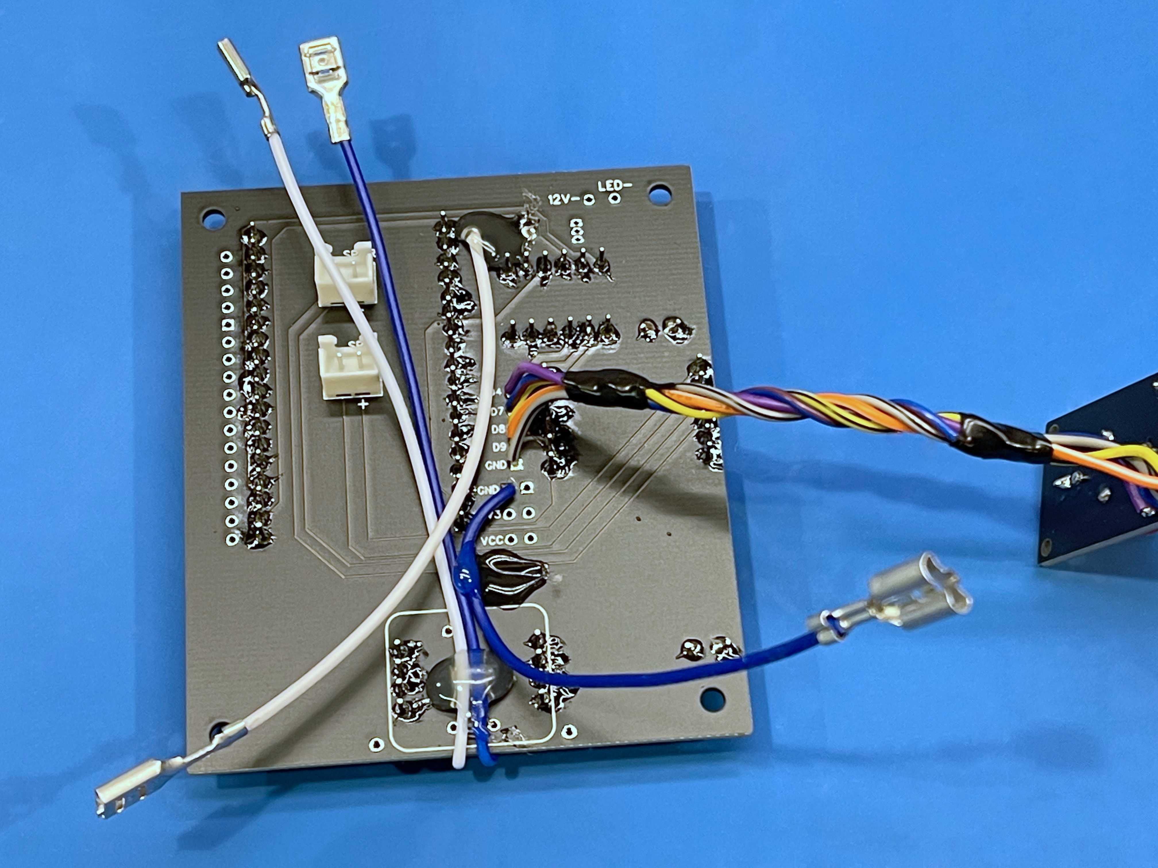
- Solder the two JST-XH female connectors to the back of the mainboard
- Mind the orientation.
- Double check your speaker wiring. The board is marked with ‘+’ symbols to indicate speaker polarity; if your speakers are wired backwards, you can fix that now by soldering these connectors upside down.
- Another piece of electrical tape is very helpful for this step (just be sure the connectors are sitting flat on the board before soldering).
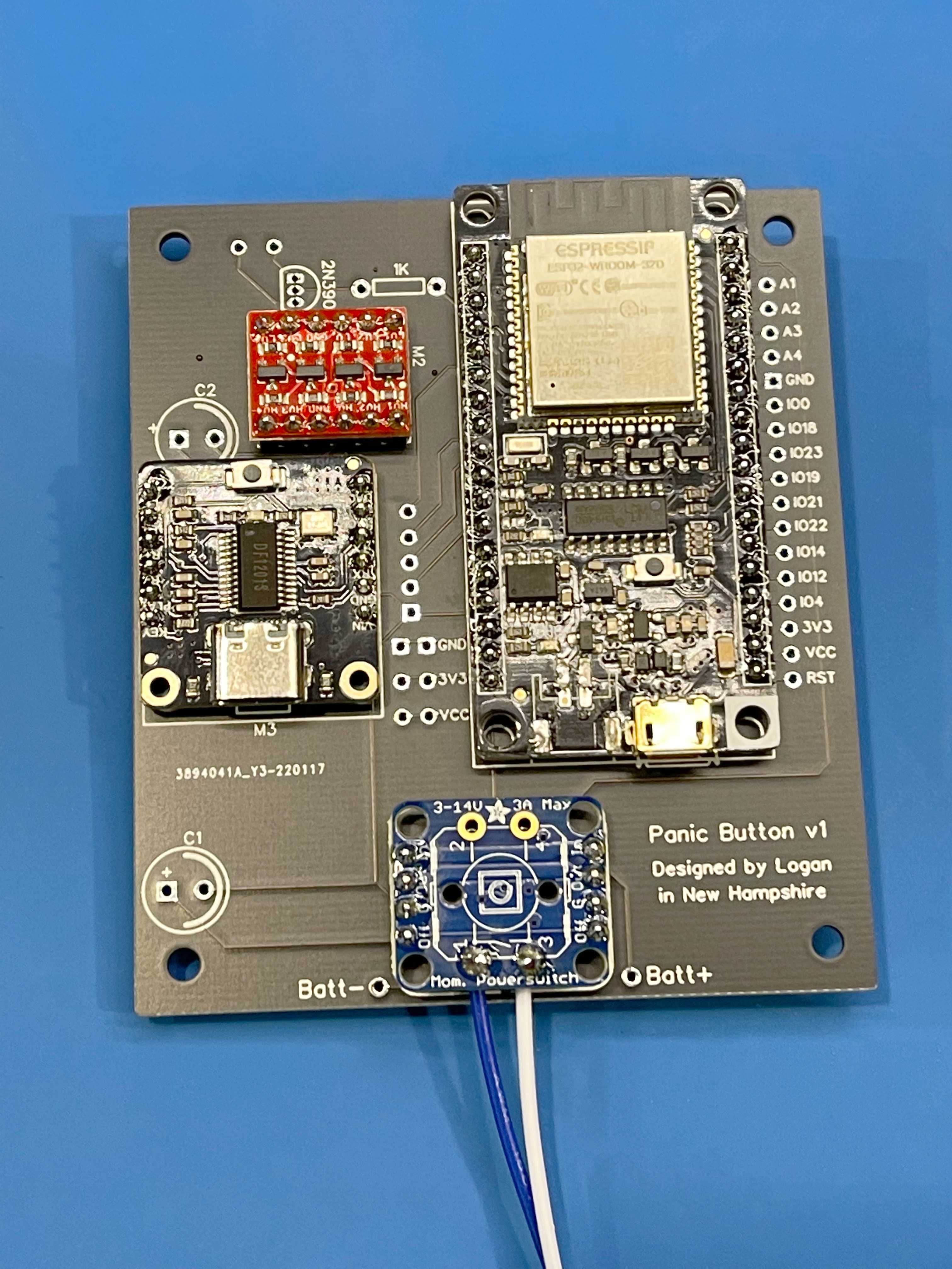
- Flip the mainboard back over and solder on the FireBeetle
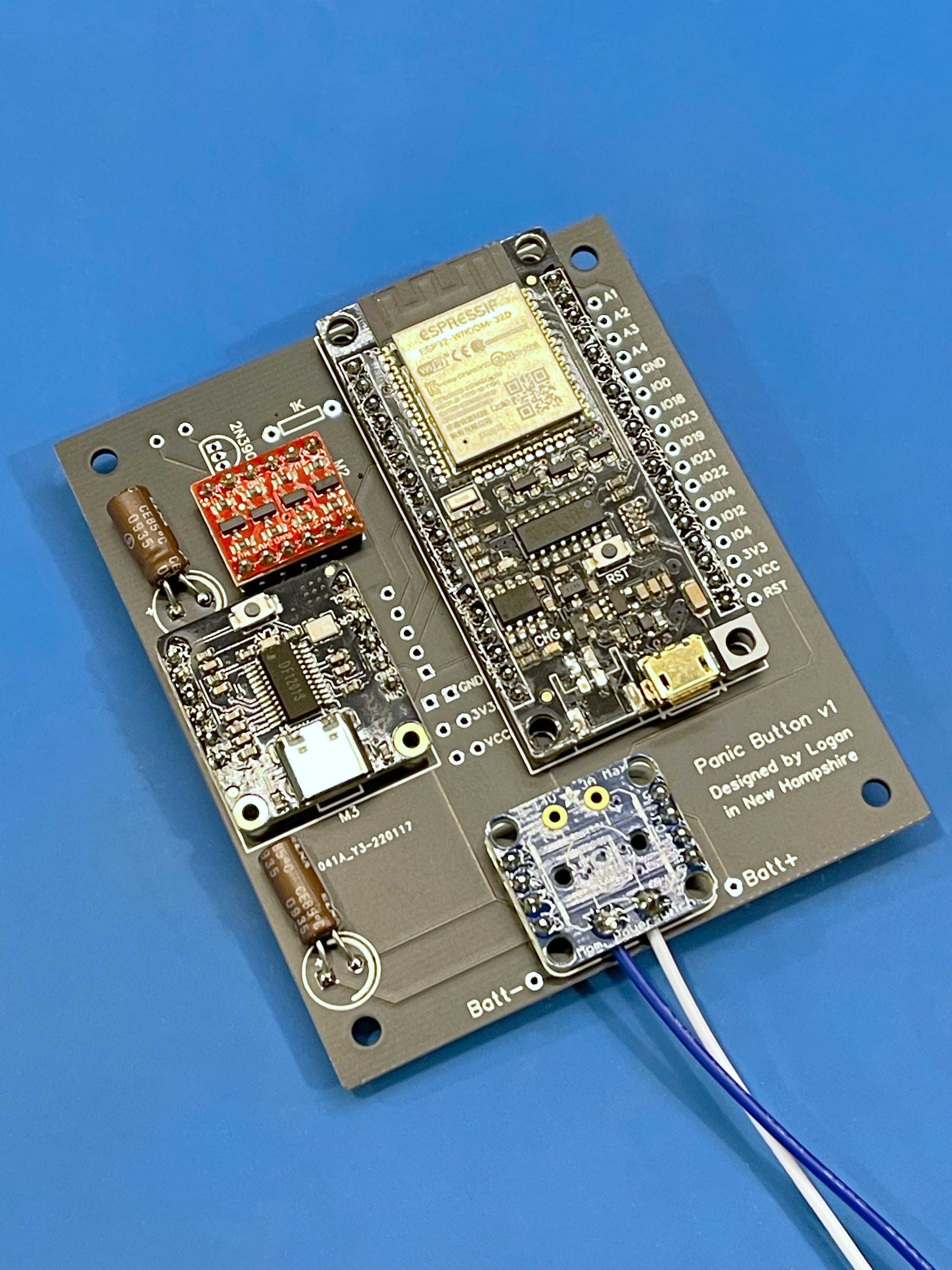
- Solder the two electrolytic capacitors to the mainboard
- They must lay flat against the board or the core will not fit in the shell.
- Solder the wires with the larger spade terminals from step #5 to the mainboard
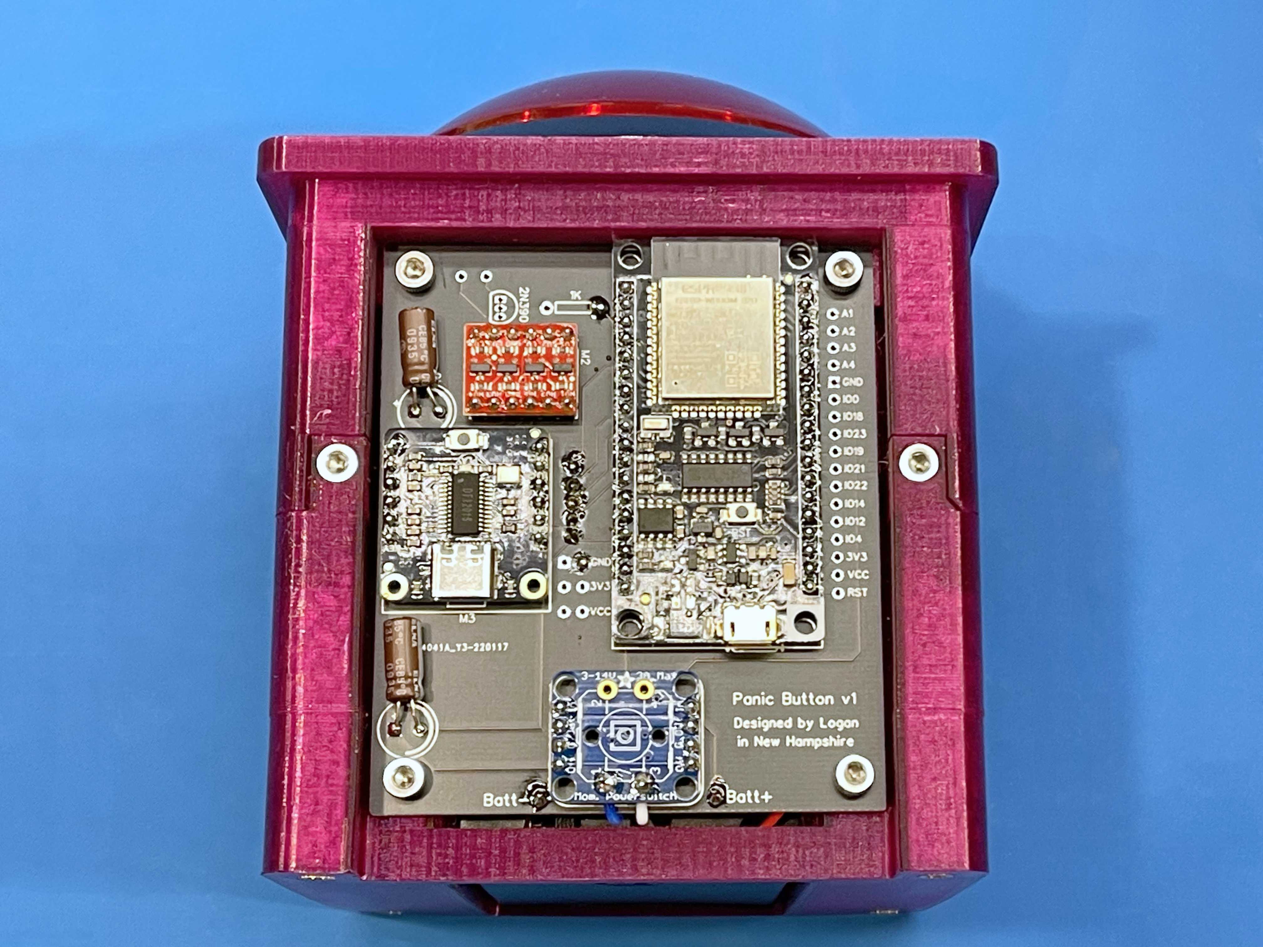
- Before I realized how easy it was to swap the LED’s resistor, I originally intended to control it with a boost module (hence the component footprints at the top of the mainboard). Luckily, despite the now-misleading silkscreen, all the terminals we need are still exposed.
- Connect one of the larger spade terminal wires to the pad for the 1K resistor closer to the FireBeetle (connected to pin D2).
- Connect the other larger spade terminal wire to one of the two spare GND pads towards the middle of the board (above two 3V3 pads).
- It doesn’t matter which wire is (+) or (-); you’ve got a 50/50 shot of getting it right the first time and if it isn’t, you can just flip the LED around in its socket.
- Preheat your hot glue gun
- You’re going to need it soon.
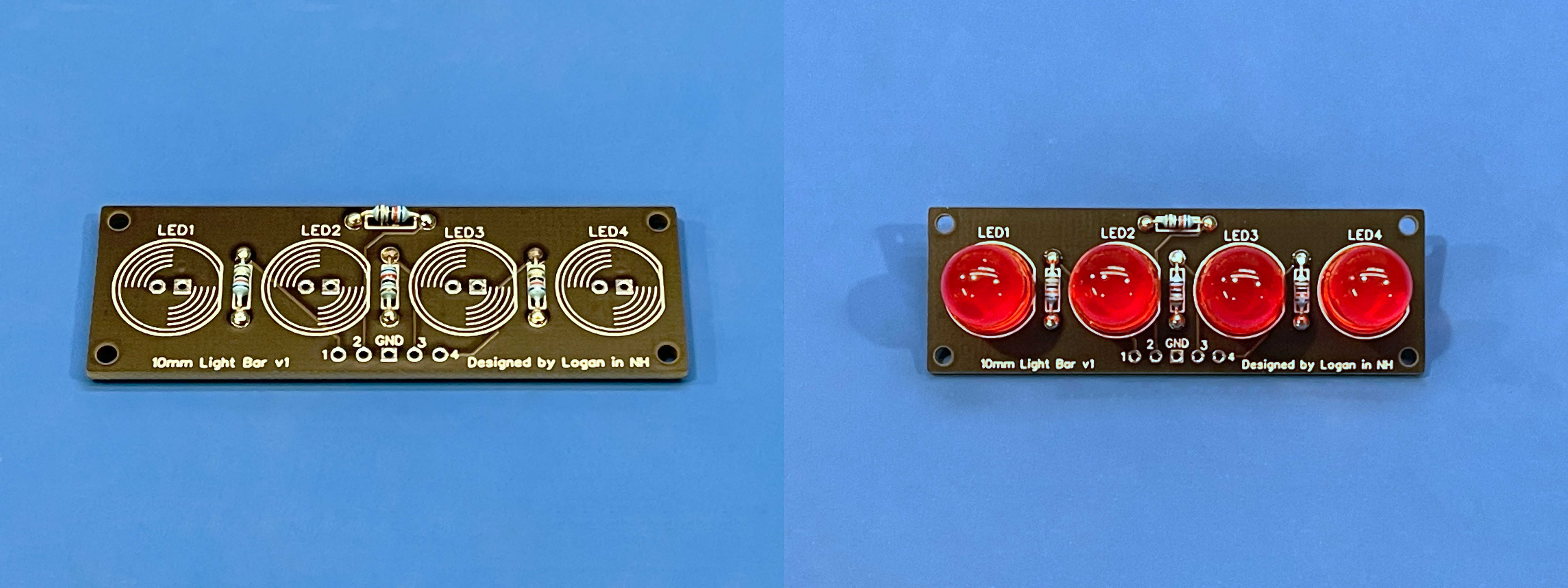
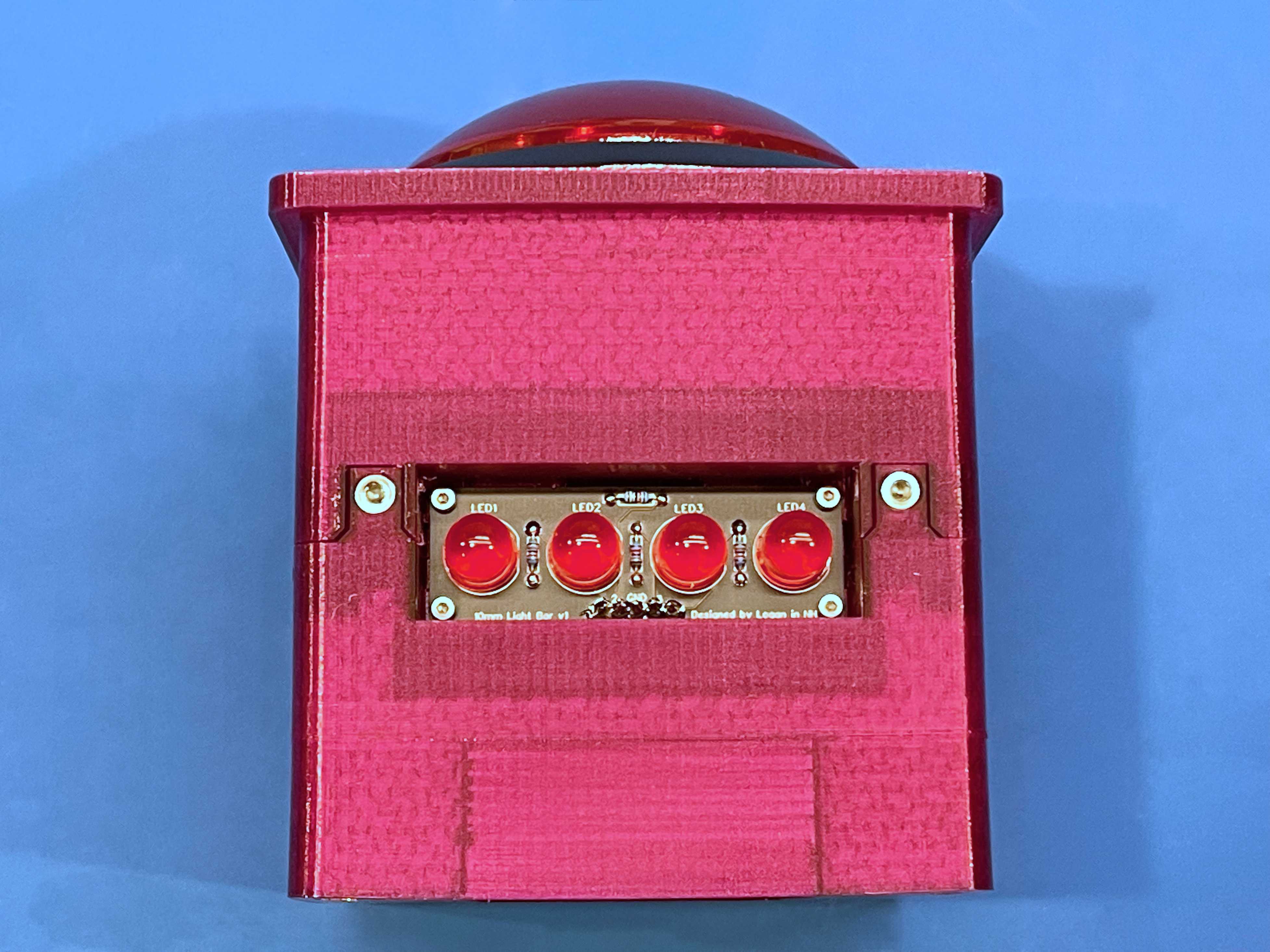
- Solder components to the LED board
- Start with the four 62 Ohm resistors, then add the LEDs.
- The LED cathodes are indicated by square solder pads (on the right when looking at the boards from the front).
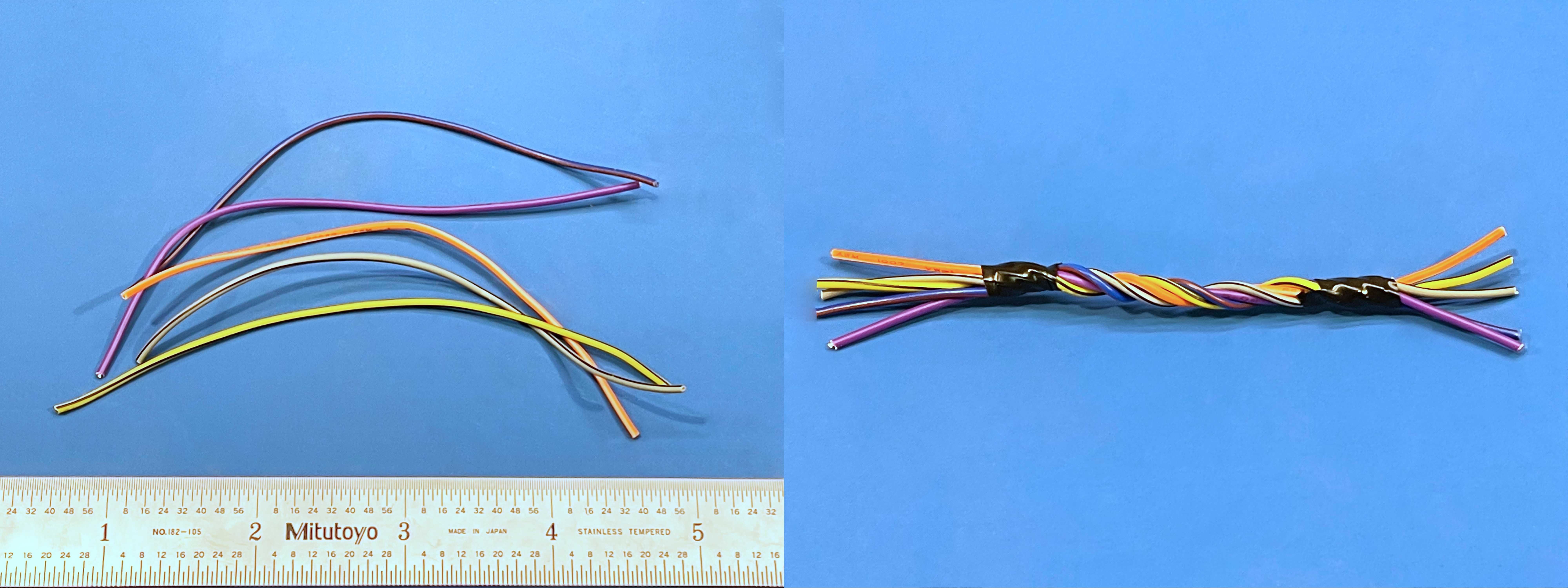
- Create the LED board wire harness
- Twist together five wires (preferably of different colors), each 4.5 inches long.
- Add a small zip tie or piece of electrical tape roughly an inch from each end to prevent unraveling.
- Strip one end (5 wires) of the harness.
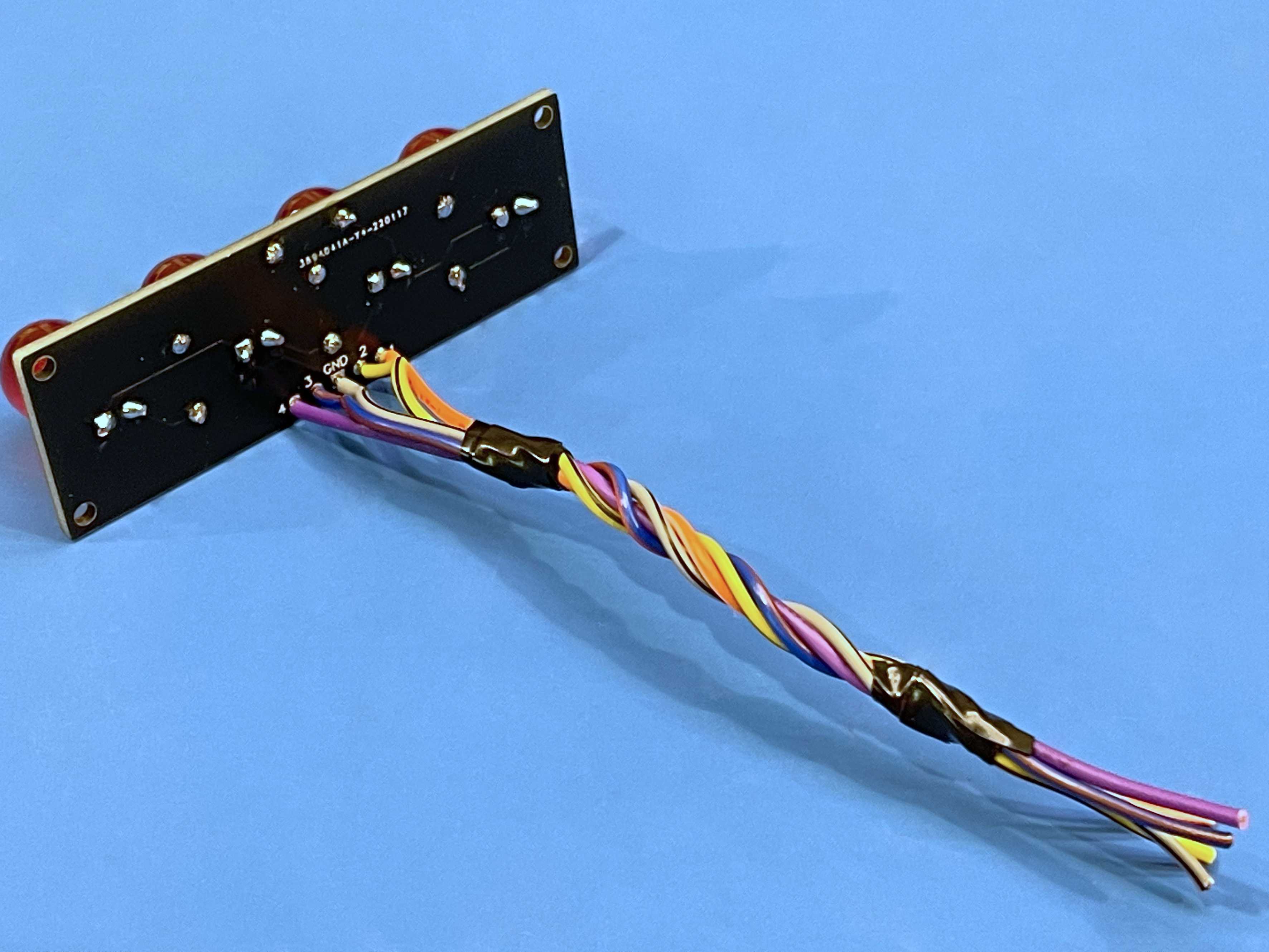
- Solder the stripped end of the wire harness to the LED board (on the side opposite the LEDs)
- Once that’s done, go ahead and strip the remaining 5 wire ends on the other side of the harness.
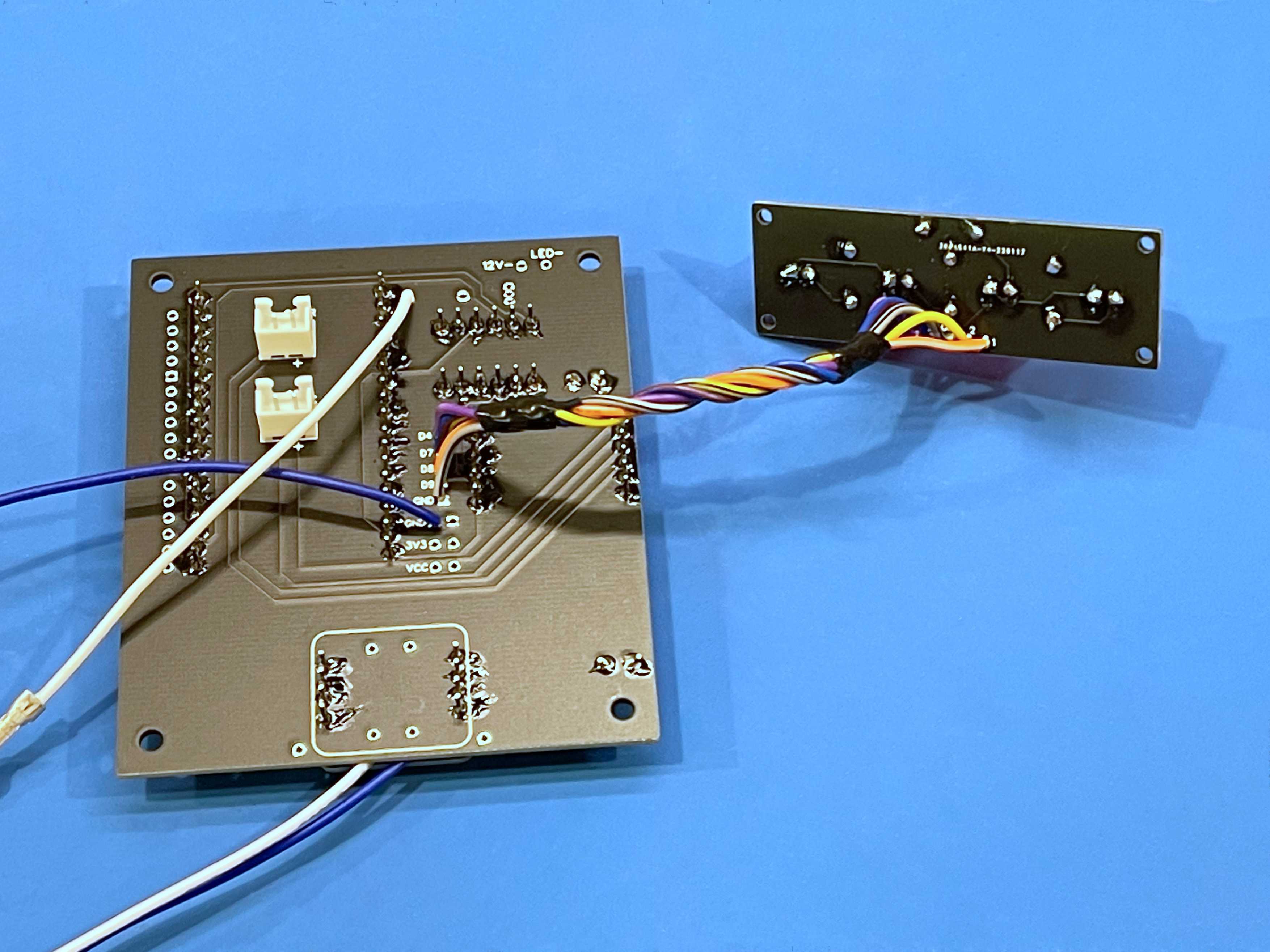
- Solder the other end of the wire harness to the vertical row of pads in the center of the back side of the mainboard
- Make a note of the mapping between LED board pads (1-4 & ground) and mainboard pads (D4, D7-9, ground); this is where different-colored wires are helpful.
- The only wire you really have to pay attention to is the ground; if you mess up the ground, at least one of your LEDs is not going to work.
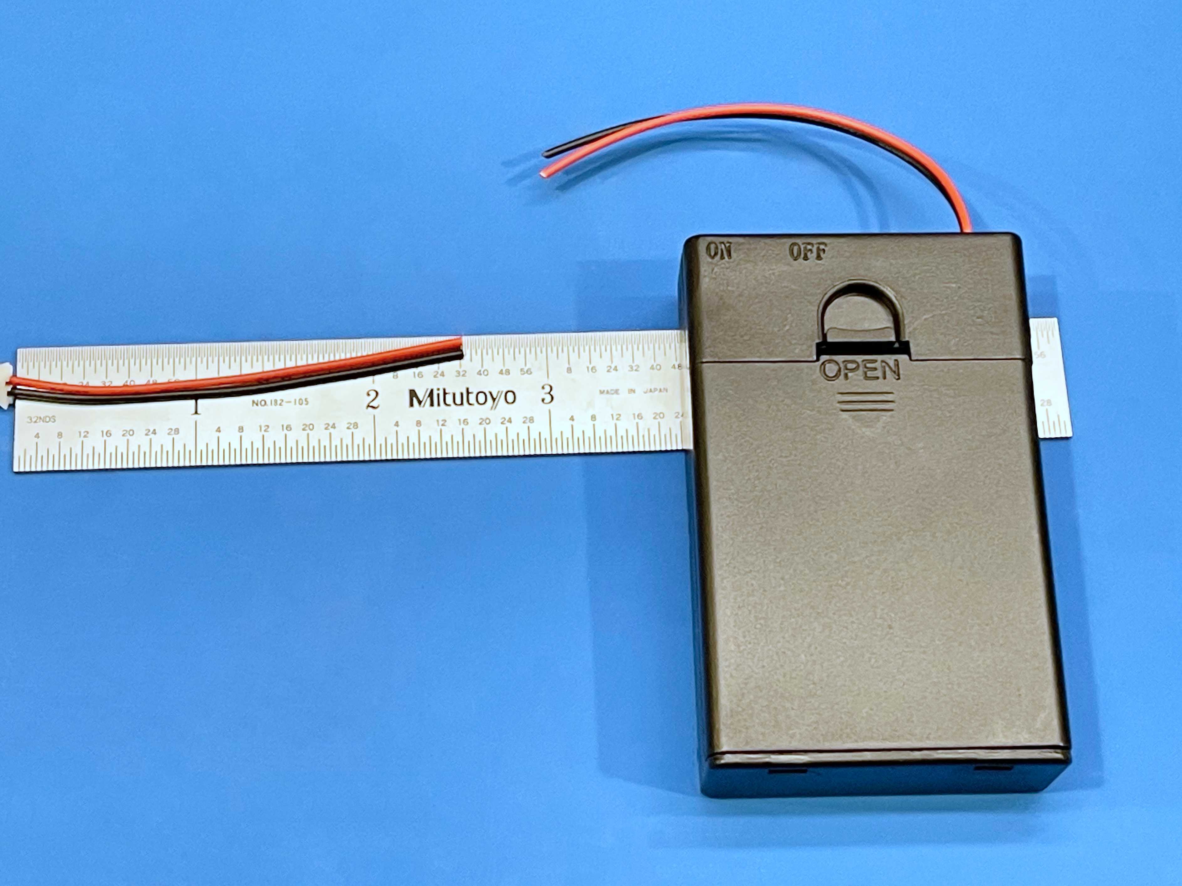
- Cut the battery holder leads about 2.5 inches from the JST connector
- We won’t be using the connector, but premade connectors like this one are handy to have kicking around for other projects.
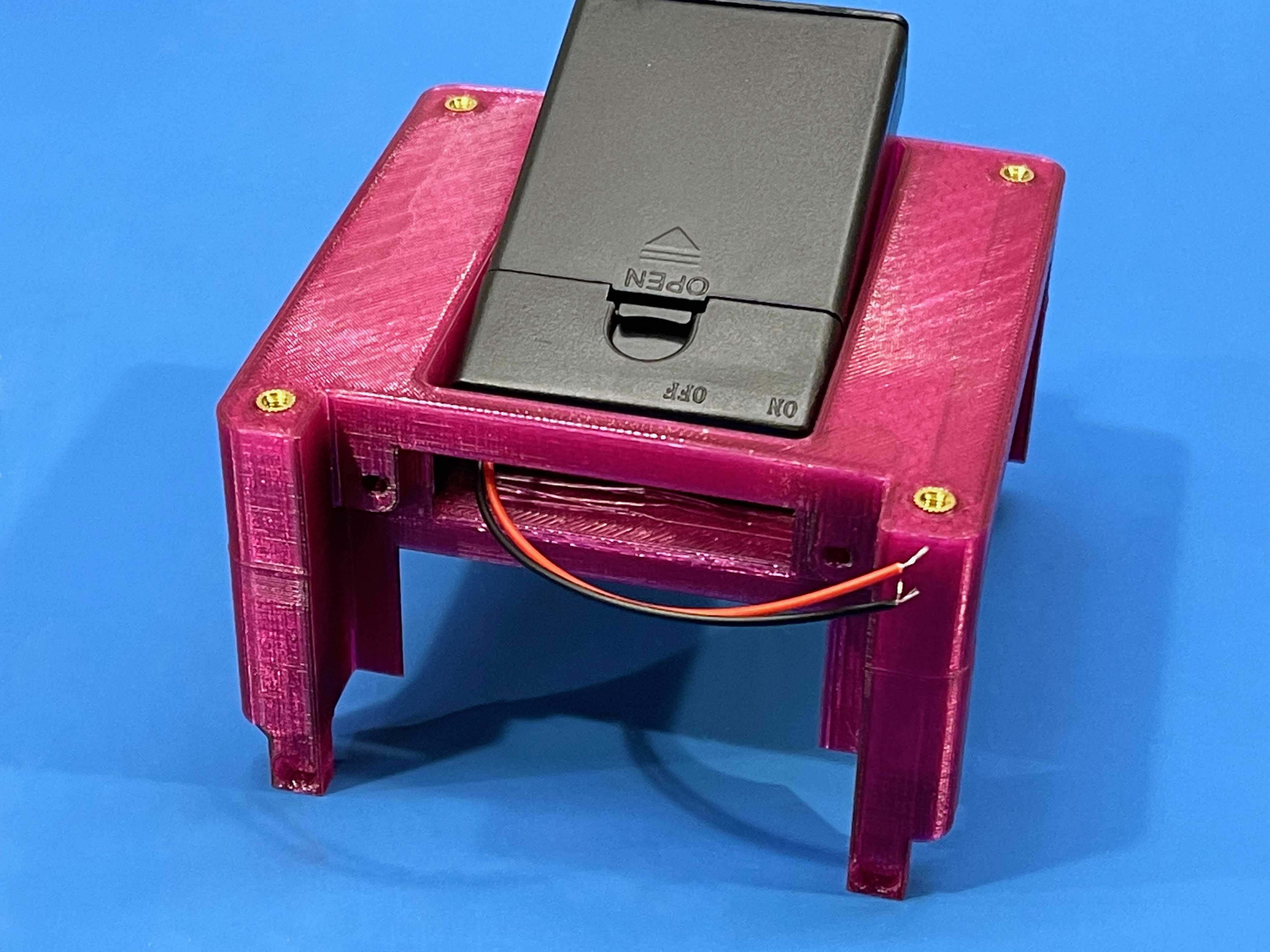
- Pass the battery holder leads through the gap in the core-bottom
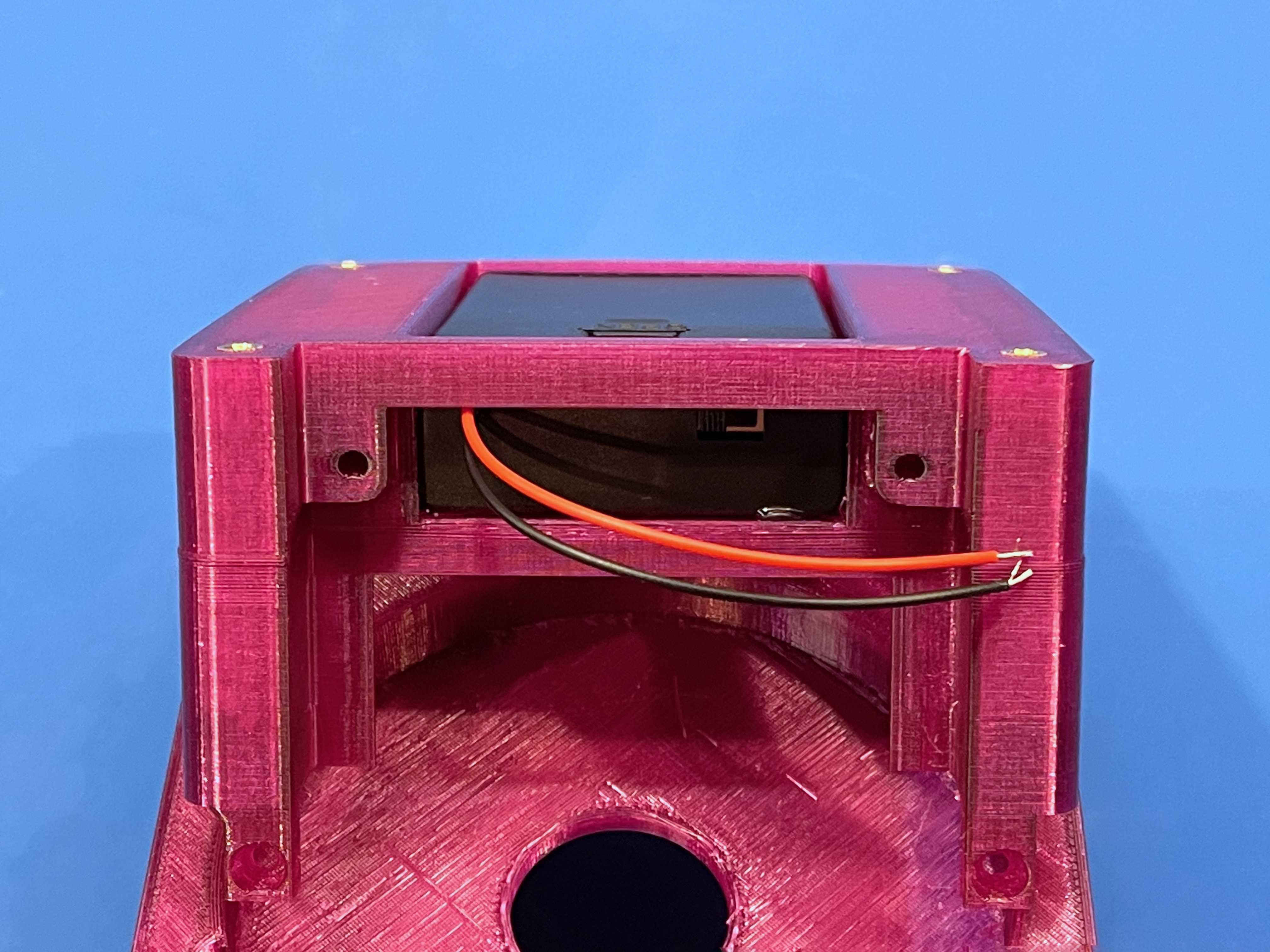
- Hot-glue the battery holder into the recess in the core-bottom
- Use caution here if the core is printed in PLA.
- Optional: Use hot glue to provide some wire management/strain relief
- Gluing the power circuit wires to the back of the mainboard (directly behind the power circuit’s footprint) seems to work well.
- The two other quick connect wires could probably also use some reinforcement.
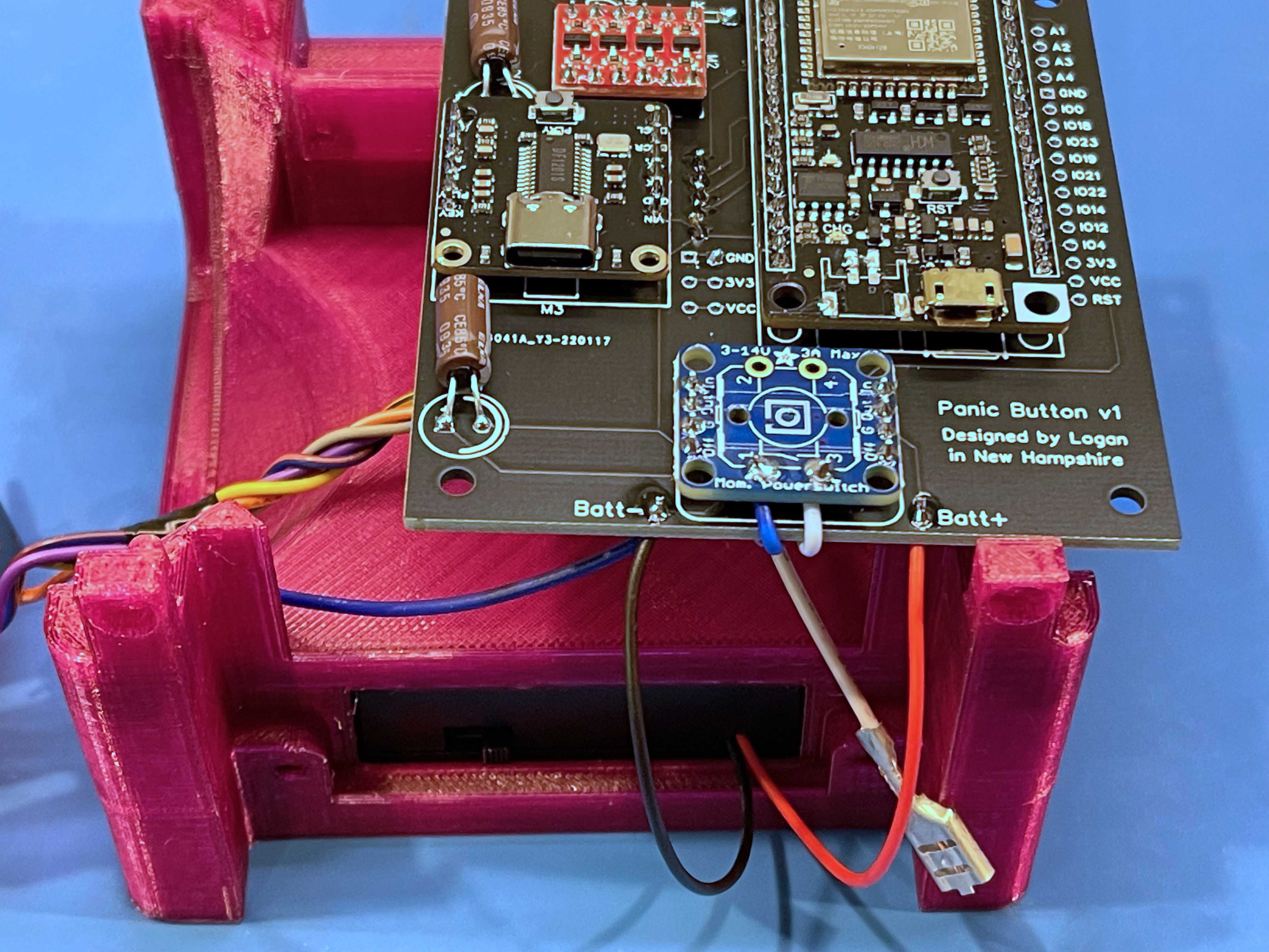
- Solder the positive and negative battery leads to the “Batt +” and “Batt -“ terminals on the mainboard
- There will be more wire here than necessary once the panic button is assembled, but in the meantime the slack makes it easier to work.
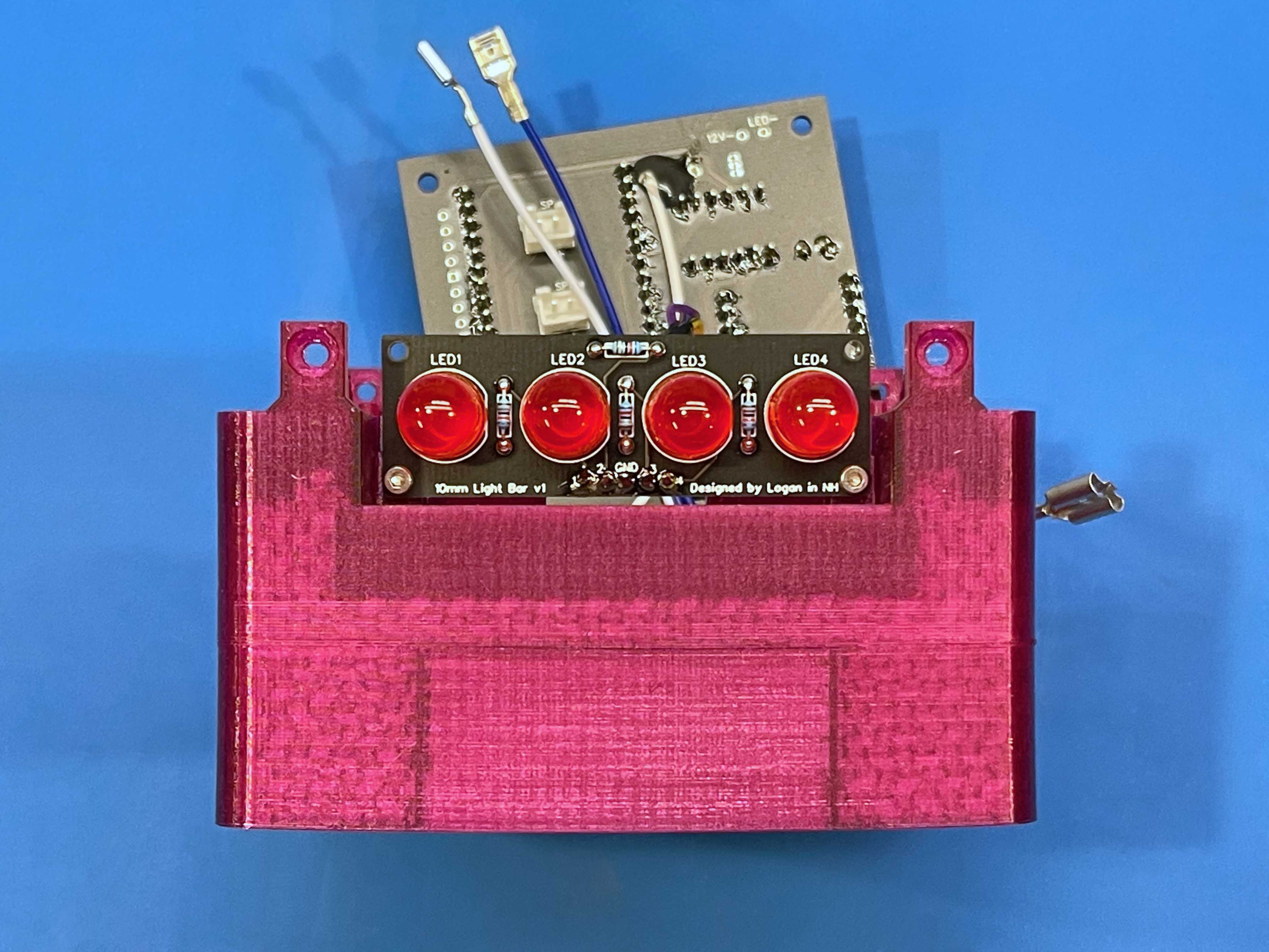
- Attach the LED board to the core-bottom with two of the M2 screws
- Take care not to overtighten these screws; they’re very small and threading directly into plastic.
- Mount the button body to the core-top
- Discard the button’s spacer ring.
- Make sure the button’s rim sits flush with the top of the core. If it doesn’t, remove it and check for leftover support material you may have missed.
- Tighten the nut down firmly.
- Connect the two sets of spade terminal quick-connects from the mainboard to the button’s switch assembly
- The wires with the smaller terminals should be routed under the bottom of the mainboard.
- You will likely want to bend the “wrists” of the larger spade terminals at approximately 45-degree angles in order to provide more space for the wires under the switch once it’s mounted.
- This is a good time to test the polarity of the button LED
- Program the FireBeetle with either the full panic button program or with a simple blink program targeting pin D2.
- If the button doesn’t light up when it should, remove the LED cartridge and reinsert it rotated 180°; retest (it should work now).
- Carefully assemble the top and bottom halves of the core
- Attach the switch assembly to the button’s stalk (the horizontal switch terminals should point towards the mainboard).
- Make sure the LED board is clearing the standoffs on the top half and that no wires are being pinched.
- Once everything is aligned properly, squeeze the two halves together. Make sure there isn’t a gap remaining between the two halves.
- Using (4) M3x8 screws, fasten the halves of the core together (again, being careful not to overtighten).
- Temporarily attach the mainboard to the core
- Use M3x8 screws in the upper right and lower left corners of the board. The upper right screw should be snug to support the insertion of speaker connectors from the back side.

- Install the right speaker
- The speaker with slightly longer wires goes on the right side (when viewed with the LED board facing you).
- Put it face-down on your work surface and route its wires through the side of the core, in front of the button stalk.
- Both speakers can be installed in any orientation, but I’d recommend orienting the right speaker’s terminals towards the front of the core.
- Plug the speaker connector into the top connector on the back of the mainboard (marked “SP-R”).
- Attach the speaker to the core using two M3x6 screws, positioned diagonally from each other. Do not fully tighten these screws yet.
- Install the left speaker
- The speaker with slightly shorter wires goes on the left side (when viewed with the LED board facing you).
- With the core resting right-speaker-down on your work surface, plug the speaker connector into the lower connector on the back of the mainboard (marked “SP-L”).
- I’d recommend orienting the left speaker’s terminals towards the back of the core (opposite orientation of the right speaker).
- Now’s a great time for a full-system test!
- If you haven’t already, program the FireBeetle and load your audio file(s) onto the DFPlayer (make sure the batteries are turned off or disconnected while you do this).
- Once programmed, turn-on or install the batteries. The circuit may power-up immediately and can be turned off by simply pressing the panic button once.
- Pressing the panic button should start the button and LED board flashing and your chosen sound should play from the speakers after a short delay.
- If anything doesn’t seem to be functioning properly, now is the time to troubleshoot.
- Install the additional M3x6 screws to finish mounting the speakers
- Get all four started before fully tightening any of them down for each speaker.
- Secure the LED board to the top half of the core using the two remaining M2 screws
- Mount the mainboard to the core using the two remaining M3x8 screws (not the longer ones)
- Feed any excess battery wire behind the mainboard (there’s plenty of space).
- Make sure no wires are being pinched or pulled.
- Once secure, test the button again to ensure everything still works.
- Note: a thin tool can be used to reach behind the mainboard and actuate the switch on the battery holder should battery power need to be disconnected (while programming, for example).
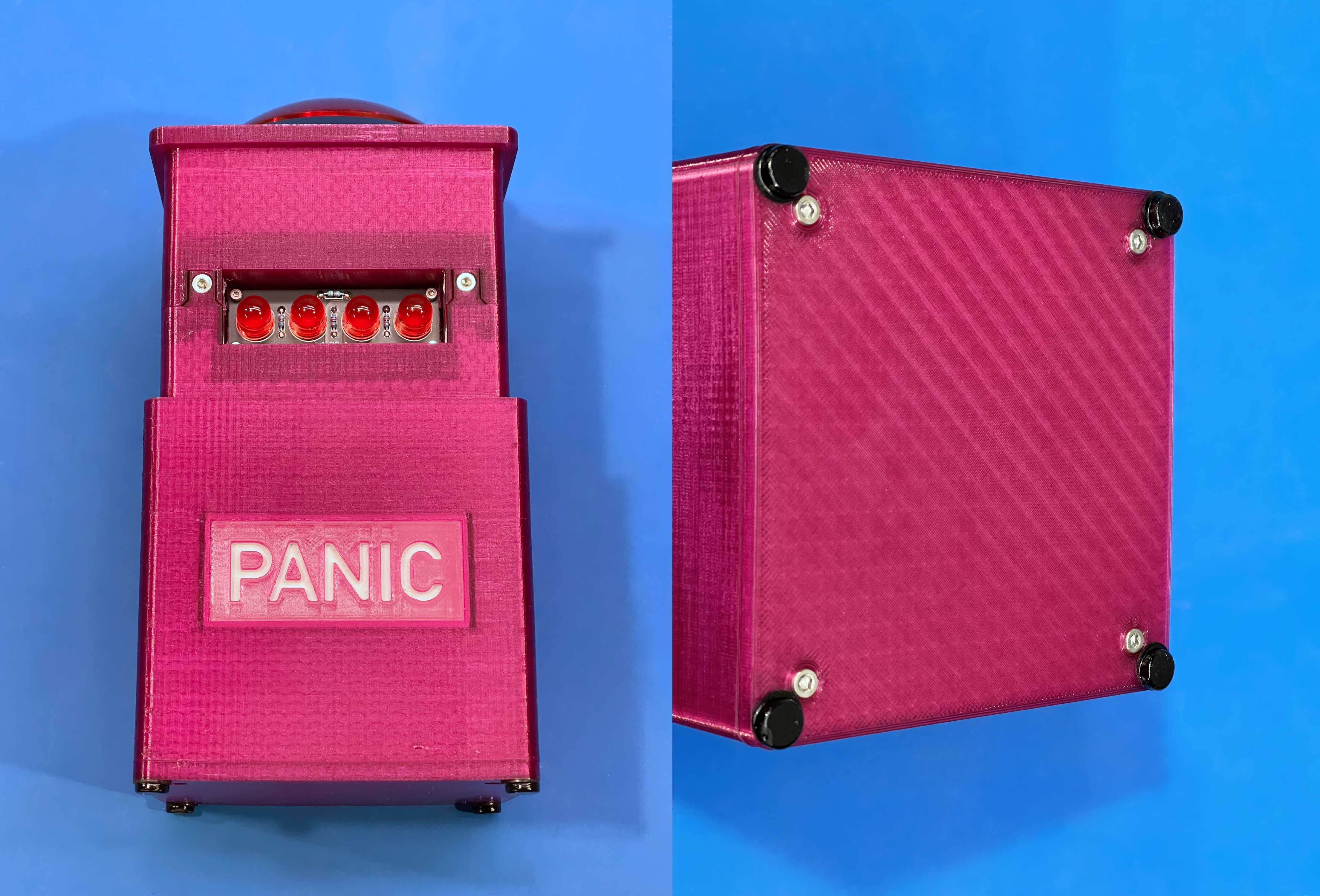
- Insert the core into the shell and screw them together
- Obviously make sure the core is oriented properly within the shell (LED board projecting towards the lithophane window).
- Use the four M3x10 screws.
- Depending on how cleanly your hole support material detached, the screws may not quite sit flush with the bottom of the shell.
- You’re done!